


What is a flange face surface?
The flange face surface is the area where the sealing element (gasket) is installed. The most common flange face surface designs are smooth and serrated. Flat face (FF) flange surfaces and raised face (RF) flange surfaces require serrations if built to industry standards.
Smooth or Serrated
Flange surface faces can be classified as smooth (also called ‘flat’ or ‘plain’) or serrated. Smooth faces appear visually ‘smooth’ and have no visual tool markings. Serrated faces have some form of tool markings on the flange face.
Flange Face Surfaces
Irrespective of which flange face surface is used, the flange assembly must be mated and tightened to the required torque in order to seal correctly.
High-temperature and high-pressure system flanges use a serrated sealing surface, or a metal gasket. Low-temperature and low-pressure system flanges may use a smooth flange face surface and soft gaskets.
Are you enjoying this article so far? Then be sure to check out our Flange Fundamentals Video Course. The course has over five hours of video content, a 52 page colour illustrated handbook (this article is an extract from the handbook), a quiz, and you will receive a certificate of completion when you finish the course. Enjoy!
Surface Finish
The ‘finish’ of a flange face surface represents the final properties of a flange’s sealing surface. A flange face may be smooth or serrated, but additional machining steps can be taken to further define the exact finish of each type of surface. For example, a flange surface may be smooth, but how smooth? A serrated flange surface has serrations, but what is the depth, number, and geometry of these serrations? These properties, and the acceptable roughness value, determine a flange surface’s finish.
Smooth Flange Surfaces Finish
Smooth flange surfaces appear to be flat and featureless when inspected visually. For flat face flanges, the smooth flange surface extends across the entire flange face. The smoothness of the surface depends upon the amount of machining the flange face has received. Metallic/hard gaskets must be mated with smooth finished surfaces otherwise a seal will be difficult to obtain.
Contrary to popular belief, a smoother surface does not necessarily mean an easier and more reliable seal. Seal integrity is determined by many factors, including -but not limited to-:
- Gasket sealing material.
- Gasket design.
- Flange construction material.
- Service conditions (temperature, pressure etc.).
- Following the correct bolting procedure.
Serrated Flange Surfaces
Serrated flange surfaces consist of concentric circular grooves, or a continuous spiral groove (also known as ‘phonographic’) machined onto the flange sealing surface. Serrated flange surfaces use non-metallic (soft) and semi-metallic gaskets.
The image below shows the two serration types. The spiral serration in the image is exaggerated because it is sometimes difficult to see the spiral shape on a real flange, due to the closeness of the serrations.

Concentric (left) and Spiral (right) Serrations
The depth of each groove, number of grooves per centimetre (or grooves per inch), and the surface roughness, are defined by published standards. For example, the ASME B16.5 standard specifies serrations of 1/64 inch (0.4 mm) deep with 32 serrations per inch (12.5 serrations per centimetre) for spiral serrated and concentric serrated flange surfaces.
Serrations provide more resistance when mating with gaskets, which ultimately leads to a lower probability of leakage as the likelihood of gasket dislocation (un-sealing) is reduced; this is true even when less sealing pressure (bolt torqueing) is applied.
The number of serrations and the depth of the serrations determine how much compressive force is required to obtain a seal. A large number of shallow serrations would effectively yield a flange surface that resembles a smooth flange surface. Less serrations, with deeper grooves, has the opposite effect
Flat face and raised face flanges usually require serrations to conform to a given standard, but the application of standards is industry and application dependent. Some industries do not use standards because the result of flange failure is of little monetary concern, or flange failure poses little/no health and safety concerns. These industries typical operate low flow, low pressure, and low temperature systems, which do not convey harmful substances (toxic, poisonous, highly corrosive etc.).
Concentric Circular Groove Flanges
Concentric circular groove surfaces are characterised by circular serrations that gradually increase in diameter as they move from the internal diameter of the flange, to the outside diameter. Serrations are cut into the surface using a cutting tool with a 90⁰ degree V-shaped tool tip and a cutting depth of 0.4 mm; the cutting tool gives the serration its geometry.
.png)
Serration Geometry, Depth and Length
Spiral Groove Flanges
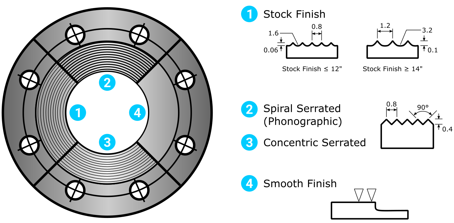
Spiral groove surfaces can be further classified as ‘stock finish’ or ‘spiral serrated’, but the difference between the two is only the serration geometry. Spiral serrated flanges have 90⁰ degree V-shaped geometry serrations. Stock finish flanges have a much shallower serration geometry because the serrations are made by a round nose cutting tool.
The most common flange surface in use today is the stock finish type due to its ease of manufacture and suitability for a wide range of applications.
Spiral groove serrations are not used with systems that convey low viscosity (low density) fluids because the probability of leakage is high. The risk of leakage is high because gasket flow must extend to the base/trough of the serration, failure to do so will allow a fluid to leak through the spiral channel until reaching the outside diameter of the gasket, and thus the ambient surrounding.
Roughness and Surface Finish
For a gasket to seal correctly, the mating flange sealing face, and the companion flange sealing face, must have suitable surfaces. Suitable surfaces are defined by their roughness value.
A flange face’s surface roughness value defines its surface finish.
The surface finish is important because it should not only assist with creating a good seal, but it should also assist in maintaining the seal. It does this by creating friction between the gasket and sealing faces, this consequently helps the gasket maintain its correct sealing position.
A ‘cold water finish’ is a very smooth surface finish (appears to have almost a mirror-like property). Cold water finished surfaces are not usually intended to mate with gaskets, they mate directly onto another cold water finished surface; this type of surface is expensive and easily damaged.
Roughness Average (Ra)
The roughness of a flange face is measured by the Roughness Average (Ra). Units of Ra are micro inches (µin), or micrometres (µm). Roughness is calculated using the Arithmetic Average Roughness Height (AARH), or Root Mean Square (rms) calculations. Both AARH and rms yield roughly the same result, and the two terms are often used interchangeably.
Suitable Roughness Values
Industry standards dictate suitable roughness values, the following is taken from the ASME B16.5 standard:
|
Surface Types |
Maximum Roughness Value |
|
Ring-type joint flanges (and hard gaskets) |
63 µin AARH (1.6 µm AARH) |
|
Spiral wound gaskets. |
125 to 250 µin AARH (3.2 to 6.3 µm AARH) |
|
Soft gaskets. |
250 to 500 µin AARH (6.3 to 12.6 µm AARH) |
|
Tongue and Groove, and small Male and Female |
125 µ.in. or 3.2 µ.m AARH |
Common Gaskets and Acceptable Roughness Values Table
Notice that the suitable flange surface roughness value increases as the gasket material softens. Thus, it can be derived that a softer gasket can seal more effectively on a rough surface than a hard gasket can. This is logical because harder gaskets require more compression energy to deform and seal, than softer gaskets.
Roughness values are usually indicated on the flange e.g. an abbreviated roughness value may be indicated as ‘125-250 AARH’ or ‘3.2 to 6.3 AARH’.
Flange Types, Faces, and Surfaces - Explained!
This video is part of our Piping Flange Fundamentals Video Course
Related Online Engineering Courses
Introduction to Valves (short course)
Introduction to Centrifugal Pumps
How Multistage Centrifugal Pumps Work
Plate Heat Exchanger Fundamentals
Introduction to Heat Exchangers
How Plate Heat Exchangers Work
Sub-Critical, Supercritical, and Ultra-Supercritical Boilers
Heat Recovery Steam Generators Explained
Additional Resources
http://www.wermac.org/flanges/flanges_raised-face_flat-face_ring-type-joint.html
https://www.kamleshmetal.com/flanges-faces-types.html
https://www.theprocesspiping.com/introduction-to-flanges